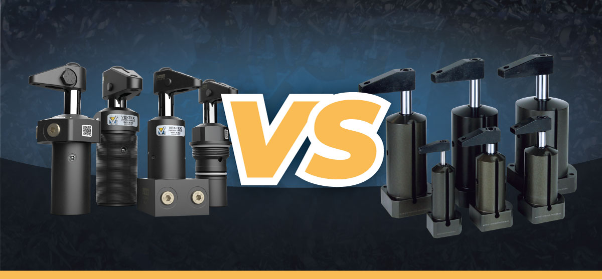
Choosing between hydraulic and pneumatic workholding depends on various factors, from clamping force and cycle time to precision and total cost of ownership. This comparison breaks down both systems by the specifications that matter most to your application, so you can match the right technology from the start.
Clamping Force and Cylinder Size
Hydraulic oil is essentially incompressible, while pneumatic air compresses under load. That single property accounts for nearly all performance differences between the two systems, starting with how much cylinder each one needs to deliver the clamping force a part requires.
Clamping force is set by the application, not the system. If a part needs 1,000 lb-f, both a hydraulic and a pneumatic fixture can be designed to deliver it. The difference is the size of the cylinder required, as clamping force equals pressure multiplied by piston area.
Because oil resists compression, hydraulic systems can build and hold far higher pressure than compressed air allows. Most standard hydraulic workholding operates at between 500 and 5,000 PSI, and some ultra-high-pressure systems can reach over 7,000 PSI. Pneumatic force for many light-to-medium machining applications comes from shop air at 80 to 120 PSI.
That pressure gap translates directly into size. In theory, producing 1,000 lb-f at 5,000 PSI takes a piston area of just 0.2 square inches, or a bore of roughly 0.5 inches. At 100 PSI, the same force takes 10 square inches, or a bore of about 3.6 inches. The pneumatic cylinder needs about 50 times the piston area to produce the same force. A hydraulic cylinder can generate the same clamping force as a pneumatic cylinder from a much smaller, more compact body.
Actuation Speed and Cycle Time
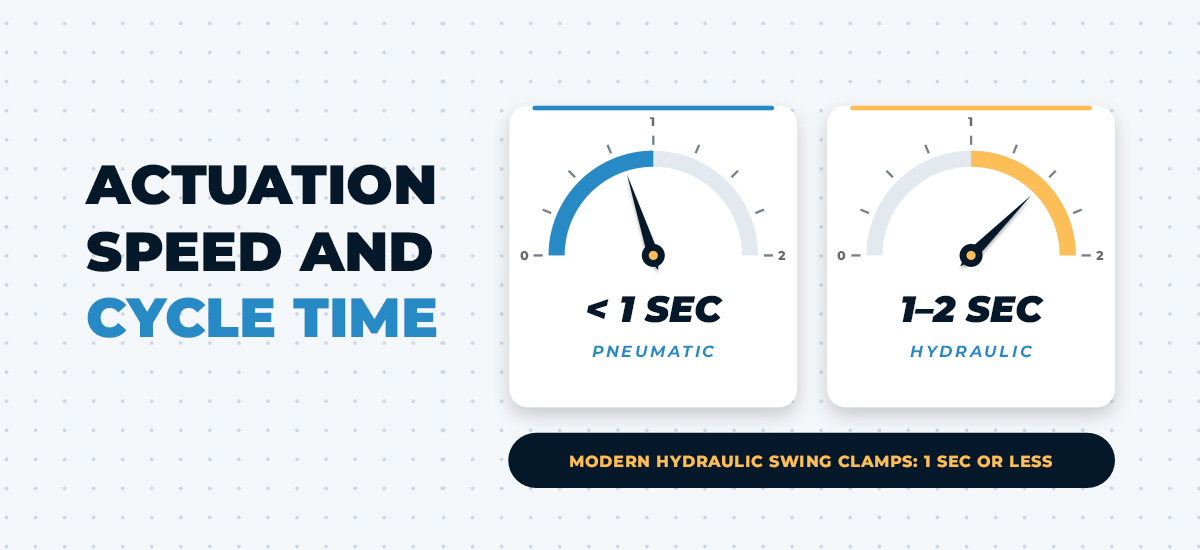
Compressed air travels through a circuit quickly, so pneumatic clamps typically actuate in under 1 second at standard shop pressure, with no circuit warmup required. Most hydraulic actuation systems run slightly slower, typically 1 to 2 seconds, depending on circuit volume, fluid viscosity and pump capacity.
Pneumatic’s speed advantage matters most in high-volume, short-cycle applications, where load and unload time make up a meaningful share of total cycle time. Across thousands of cycles per shift, even fractions of a second compound into real throughput gains.
Hydraulic systems’ slower actuation comes with its own time value. Consistent, repeatable force at the moment of contact means greater degrees of process and quality control. Modern hydraulic swing clamp designs have considerably narrowed the speed gap, with some models actuating in 1 second or less with ±0.25 degrees of repeatability.
System Footprint and Space Requirements
At the system level, a pneumatic circuit has the opportunity to connect to existing shop air lines, requires no dedicated power unit and adds minimal infrastructure to your facility. Hydraulic systems require a dedicated power unit, including a pump, reservoir and often a cooling system, along with high-pressure plumbing routed to the fixture. That power unit is usually positioned remotely, but it still adds floor space and complexity that pneumatic systems avoid.
Footprint at the clamp level looks different. Because hydraulic pressure can be designed to deliver pressure more efficiently in a compact system, it delivers significantly higher force from a smaller actuator body. Pneumatic requires a larger bore to generate an equivalent force. In high-density, multipoint fixtures and 4- or 5-axis machining environments, a hydraulic system’s compact per-clamp profile often improves tool access clearance.
Air and Fluid Supply Infrastructure
Pneumatic workholding often uses compressed air that is already available in most facilities. However, air loses pressure as it travels through pipes, fittings and valves. This loss may be due to moisture, particulates and temperature fluctuations. A pressure drop weakens the clamping force by the time the air reaches the fixture. Filtration, drying and regulation solve these problems, but each one adds a part to install and maintain.
Hydraulic workholding requires a dedicated power unit, including a pump, reservoir, manifold and high-pressure-rated tubing and fittings. Once installed, that power unit delivers consistent, demand-independent pressure.
Precision, Rigidity and Deflection Control
Research on machining deformation identifies clamping force as a primary driver of dimensional accuracy. Insufficient force allows the workpiece to move during cutting, while excessive force causes elastic deformation, preload and unintended part movement. The same peer-reviewed study on machining deformation notes that conventional clamping settings based on manual experience carry significant uncertainty.
Hydraulic oil’s incompressibility keeps the clamping force constant and nonyielding throughout the machining cycle, and that force does not fluctuate during interrupted cuts or vibration. Contrastingly, pneumatic force is bounded by air compressibility. It can creep or drop under sustained load or line-pressure variation, which can manifest as dimensional variation in finished parts.
For many general-tolerance applications, pneumatic clamping is adequate. The gap between the two systems becomes more significant as tolerances tighten and cutting forces increase. Reaching high precision at high cutting forces with pneumatic clamping is possible under specialized design conditions, but that level of control requires engineering well beyond what standard components can provide. When tolerances tighten, hydraulic’s rigidity is typically the more reliable foundation.
Component Support for Precision-Critical Fixturing
Clamps alone don’t always control deflection on complex or irregular geometries. Work supports add reinforcement beneath the part, keeping it from flexing or shifting under clamping and cutting forces, especially on thin-walled sections or castings. In a hydraulic fixture, the same pressurized oil that actuates the clamps also locks the supports in place. Because oil is incompressible, a locked support resists the clamp’s downward force without yielding.
One drilling application on cast aluminum intake manifolds shows how this works. Cast parts vary slightly in size, so each support has to adjust to the part and then lock firmly. If it doesn’t, clamp force can push the part out of position and shift the hole. The original supports were locked by hand with a screw. Researchers replaced them with hydraulic work supports and ran the clamps and supports at 40 bar (about 580 PSI). The workpiece did not move under clamping force, and the average hole center deviation was 0.145 mm against a 0.5 mm limit.
The hydraulic supports also made the fixture automatable. Operators no longer had to hand-lock each support, which cut fixture setup time and reduced rejected parts. Output rose from 27 to 36 parts per shift, an increase of 33.33%. The gain came from faster setup and fewer rejects, not from faster drilling.
Some modern work supports offer positional accuracy with repeatability up to 0.00508 mm (±0.0002 inches), ensuring consistent results across demanding applications.
Cost of Ownership, Maintenance and Reliability
Cost comparisons between hydraulic and pneumatic workholding depend heavily on timeline and production volume. Purchase price is only one piece. Energy, upkeep and reliability all shape what a system costs over a fixture’s service life.
Pneumatic hardware carries a lower up-front cost. It runs on existing shop air, and installation is minimal. Hydraulic systems require a dedicated power unit and high-pressure plumbing, a meaningful capital commitment, especially for shops without an existing hydraulic circuit.
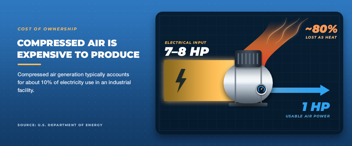
Over time, the cost picture can shift because compressed air is expensive to produce. According to the Department of Energy, compressed air generation typically accounts for about 10% of electricity use in an industrial facility, and 30% or more at some facilities. Overall system efficiency can run as low as 10% to 15%, and roughly 7 to 8 horsepower of electrical input is needed at the compressor to deliver 1 horsepower of usable air power.
About 80% of the electrical energy supplied to an air compressor is lost as heat during compression. Air leaks add to these costs. They are common in pneumatic circuits, and because clamping force depends on a continuous air supply, every leak makes the compressor work harder. Day-to-day pneumatic maintenance is simpler and cleaner, since there’s no risk of oil contamination, but the filtration, drying and regulation equipment that protects clamping force still needs regular attention.
Hydraulic workholding requires more rigorous maintenance, including fluid monitoring, seal inspection and contamination control. Contamination can damage valves, so scheduled fluid changes are essential. Seals also wear over time, so leaks are a risk to watch for. In exchange, hydraulic systems avoid the compressor losses described above. Once a hydraulic circuit reaches pressure, holding it takes little energy, though actual consumption depends on how the power unit is designed.
Reliability under power loss differs, too. Most hydraulic systems maintain clamping force after a power loss through hydraulic lock, an advantage wherever power interruption is a risk. Pneumatic systems often release when air pressure drops, so safety-critical setups typically require a fail-safe clamp design or a pilot-check valve.
The right balance depends on how long the fixture will run, how many cycles it will see and how costly an unplanned loss of clamping force would be. Pneumatic offers a lower entry cost and simpler upkeep. Hydraulic asks for a larger investment and more disciplined maintenance, and in return delivers stable force and fail-safe holding.
Air vs. Hydraulic Clamping Overview
| Dimension | Hydraulic | Pneumatic |
|---|---|---|
| Clamping force output | Up to 5,000 PSI standard, delivering high force from a compact cylinder | 30 to 250 PSI with an intensifier, requiring a larger bore for equivalent force |
| Response speed | 1 to 1.5 seconds, with modern designs reaching 1 second or less | Under 1 second at standard shop pressure, with no circuit warmup required |
| Footprint/space | Larger system footprint from the power unit, smaller footprint per clamp | Smaller system footprint overall, larger footprint per clamp |
| Power supply requirements | Dedicated power unit with pump, reservoir and plumbing | Shop air connection, dependent on point-of-use pressure |
| Cost of ownership | Higher up-front cost, lower long-term energy cost per unit of force | Lower up-front cost, higher long-term energy costs due to compressor inefficiency |
| Precision and rigidity | Constant, nonyielding force ideal for tight tolerances | Adequate for general tolerances, limited by air compressibility under load and holistic system design |
| Maintenance | Requires fluid monitoring, seal inspection and contamination control, but maintains force after power loss | Simpler, cleaner upkeep, but depends on continuous air supply and is prone to cost-accumulating leaks |
Pros and Cons of Each Workholding System
Learn more about the advantages and disadvantages of hydraulic and pneumatic clamping systems.
Hydraulic Workholding Pros and Cons
Hydraulic workholding pros center on force, stability and precision, while the cons mostly come down to cost and complexity.
Pros include:
- High clamping force from a compact footprint.
- Consistent, stable force under dynamic cutting loads.
- Locking valves that trap working pressure in the clamp, maintaining force independent of the power unit.
- Support for tight geometric dimensioning and tolerancing (GD&T) and deflection control.
- Simultaneous multiclamp actuation.
- Automation-ready design.
Cons of hydraulic workholding include:
- Higher up-front capital cost.
- Dedicated power unit and high-pressure plumbing required.
- Fluid maintenance, including contamination control and seal inspection.
- Fluid leak risk.
Pneumatic Workholding Pros and Cons
Pneumatic systems trade some force and rigidity for speed and simplicity, favoring applications where cycle time and ease of installation outweigh the need for maximum force.
Pros of pneumatic clamping include:
- Faster clamp and unclamp cycle times.
- Simpler installation and setup.
- Lower up front cost.
- No oil contamination risk, therefore, suitable for clean or sensitive environments.
Cons of pneumatic workholding include:
- Lower force output.
- Reduced rigidity under dynamic loads due to air compressibility limits.
- Continuous air supply is necessary to maintain clamping force.
- Poor energy efficiency.
- Compound operating costs over time due to air leaks.
Which System Is Right for Your Application?
Both pneumatic and hydraulic clamping systems are invaluable across numerous industries, including manufacturing, construction, aerospace, automotive, material handling and process automation. Once you have weighed the trade-offs, the right choice comes down to matching your application to the right system.
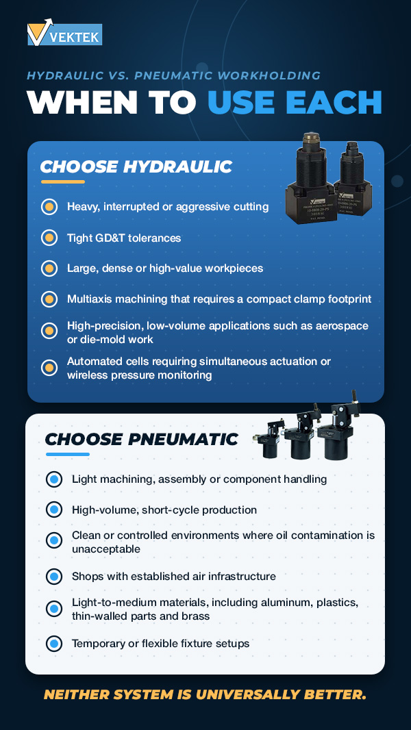
When to Choose Hydraulic Workholding
Hydraulic workholding is the right call for:
- Heavy, interrupted or aggressive cutting operations where force stability is nonnegotiable.
- Tight GD&T tolerances where workpiece deflection affects dimensional accuracy.
- Large, dense or high-value workpieces, including steel, cast iron and large aluminum castings.
- Multiaxis machining that requires a compact clamp footprint.
- High-precision, low-volume applications such as aerospace or die-mold work.
- Automated cells requiring simultaneous actuation or wireless pressure monitoring.
When to Choose Pneumatic Workholding
Pneumatic workholding is best for:
- Light machining, assembly or component handling where maximum force is not the constraint.
- High-volume, short-cycle production where load and unload speed drives throughput.
- Clean or controlled environments where oil contamination is unacceptable.
- Shops with established air infrastructure and a limited hydraulic capital budget.
- Light-to-medium materials, including aluminum, plastics, thin-walled parts and brass.
- Temporary or flexible fixture setups where portability and simplicity matter.
Frequently Asked Questions
Here are answers to some of the questions that come up most frequently about hydraulic versus air clamping.
Is pneumatic workholding better than hydraulic?
Neither system is universally better. Pneumatic offers faster cycle times, simpler setup and lower up-front cost, making it the right choice for light machining, high-volume cycling and clean environments. Hydraulic delivers greater clamping force, rigidity and precision, making it the right choice for demanding tolerances, heavy cutting and deflection-critical applications. The correct system is the one matched to your specific application requirements.
Which is stronger, hydraulic or pneumatic workholding?
Hydraulic is significantly stronger. Standard hydraulic workholding systems operate at up to 5,000 PSI, while pneumatic systems typically run at 30 to 250 PSI with an intensifier, a substantial pressure difference. For an equivalent clamping force, a pneumatic cylinder must be considerably larger than its hydraulic counterpart.
Under dynamic cutting loads, hydraulic force remains locked and stable, while pneumatic force stays bounded by air compressibility.
Why Trust Vektek for All Your Workholding Needs
At Vektek, we have spent decades helping different companies and workshops work through workholding challenges. Engineers trust us because of our:
- Decades of experience: Vektek brings decades of application-specific experience in both hydraulic and pneumatic workholding to every project.
- Free application engineering support: Our engineering team reviews fixture concepts, analyzes clamping force requirements and recommends products at no charge.
- Balanced expertise across both systems: We manufacture both hydraulic and pneumatic workholding, so we can guide you toward the best method for your applications.
Get Application Engineering Support From Vektek
Hydraulic and pneumatic workholding each brings distinct advantages across clamping force, cycle time, precision and cost of ownership. The right choice comes down to matching those specifications to your application.
If you still have questions about clamping force requirements, fixture design or which product fits your setup, talk to Vektek’s application engineering team for a no-charge review of your concept and a product recommendation. For more complex integration needs, including automation, rotary unions or pallet pool systems, our services and integration team can help you build out the full solution.