
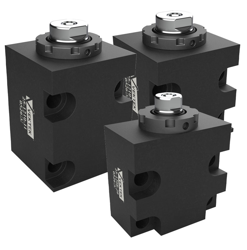
NEW! Manifold Mount Double Acting Part Crowder
Part Crowders
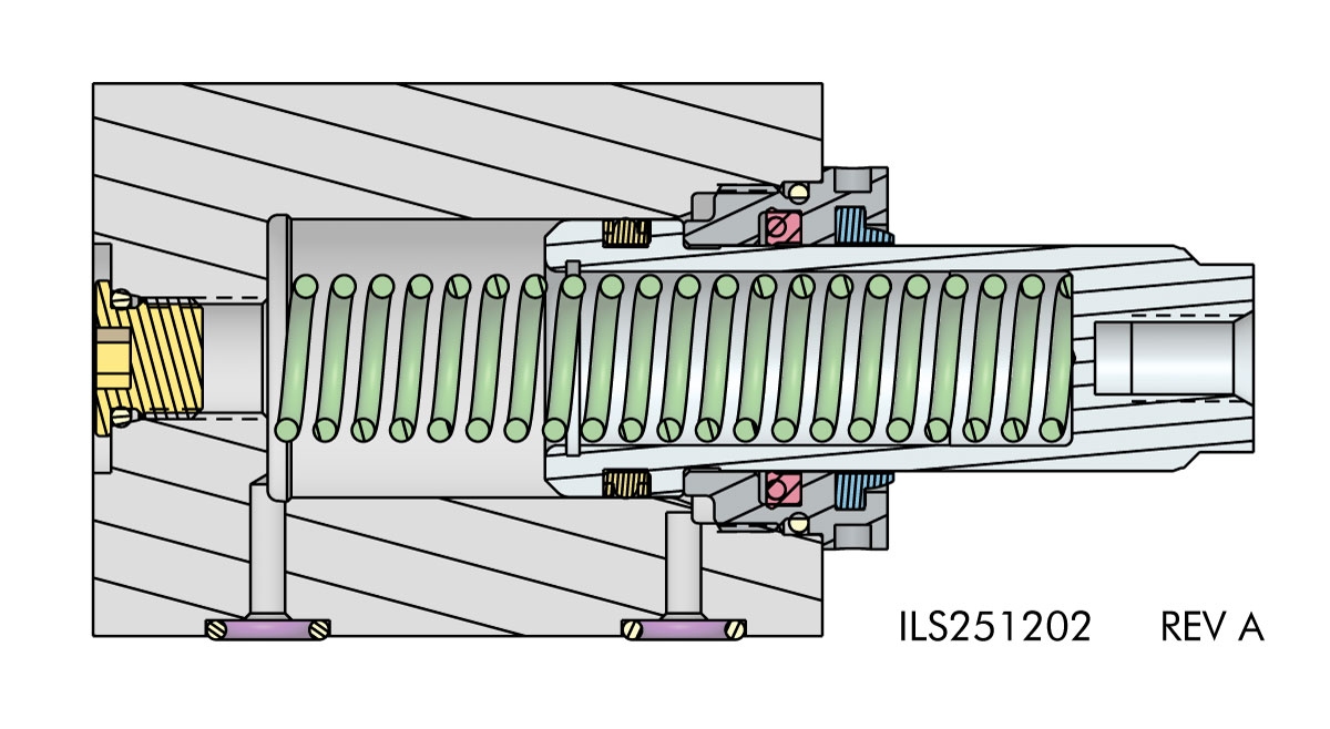
- Full Retraction for Clear Robot Access. Double-acting design retracts completely for unobstructed loading and unloading.
- Spring Contact, Hydraulic Hold. Applies low spring force for initial part control, then transitions to high-force hydraulic clamping when pressure is applied.
- Crowds and Clamps in One Device. Eliminates separate crowding and clamping components by performing both functions with a single device.
- Model Range Matches Part Size. Low spring force in compact models and higher spring force in larger units, allows selection based on part mass and rigidity.
- Manifold Mount for Lower Profile.
*Spring Force = Full Stroke Force + (Spring Rate × Compression)
Where:
Full Stroke Force (lbs): The spring force when the cylinder is at its full-stroke (fully extended) reference position.
Spring Rate (lbs/in): The increase in force per inch of additional compression.
Compression (in): The distance the cylinder is compressed from the full-stroke position.
**Cylinder capacities are listed at 5000 psi maximum operating pressure. The output force is adjustable by varying the hydraulic system pressure. To determine the approximate output force for your application, multiply the Piston Area times Your System Operating Pressure. (Actual force may vary slightly due to friction loss, seal and wiper drag, and/or return springs.)
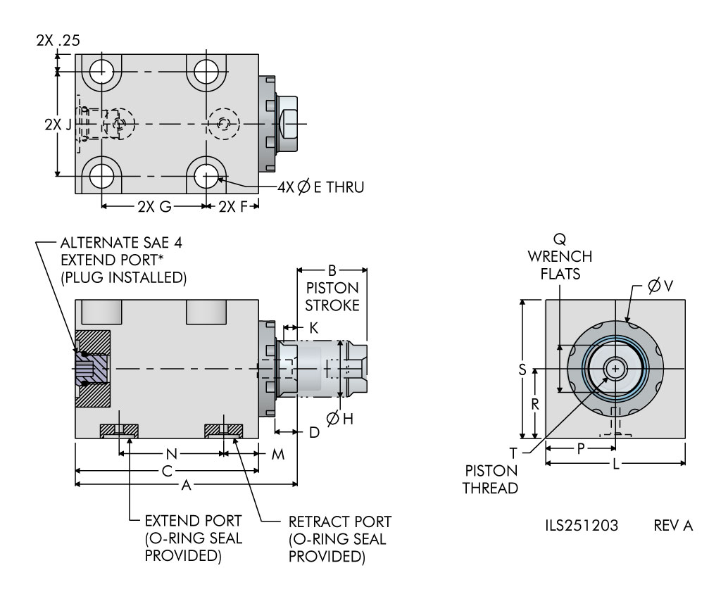
For proper sealing, the mating surfaces must be flat within 0.003 with a maximum surface roughness of 63 µ in Ra.
| Model No. | Clamp Capacity (lb.) Extend | Clamp Capacity (lb.) Retract | Stroke | Spring Force (lb.) | Std Spring Rate (lb./in.) | Body Size | Minimum Length (in) | Piston Area (sq. in.) Extend | Piston Area (sq. in.) Retract | Oil Capacity Extend (cu. in.) | Oil Capacity Retract (cu. in.) |
|---|---|---|---|---|---|---|---|---|---|---|---|
| 25-1208-20 | 2,200 | 1,200 | 0.25 | 5.0 | 50 | 1.13 x 2.00 | 2.40 | 0.442 | 0.246 | 0.110 | 0.061 |
| 25-1208-21 | 2,200 | 1,200 | 0.75 | 5.0 | 26 | 1.13 x 2.00 | 3.15 | 0.442 | 0.246 | 0.330 | 0.183 |
| 25-1210-20 | 3,900 | 1,300 | 0.50 | 5.0 | 45 | 2.00 x 2.00 | 2.69 | 0.785 | 0.267 | 0.393 | 0.134 |
| 25-1210-21 | 3,900 | 1,300 | 1.00 | 5.0 | 43 | 2.00 x 2.00 | 3.19 | 0.785 | 0.267 | 0.785 | 0.268 |
| 25-1210-22 | 3,900 | 1,300 | 2.00 | 5.0 | 23 | 2.00 x 2.00 | 4.31 | 0.785 | 0.267 | 1.570 | 0.536 |
| 25-1215-21 | 8,800 | 3,800 | 1.00 | 5.0 | 42 | 2.00 x 2.50 | 3.27 | 1.767 | 0.773 | 1.767 | 0.774 |
| 25-1215-22 | 8,800 | 3,800 | 2.00 | 10.0 | 30 | 2.00 x 2.50 | 4.27 | 1.767 | 0.773 | 3.534 | 1.548 |
| Model No. | A | B | C | D | E | F | G | H | J | K | L | M | N | P | Q | R | S | T | V |
|---|---|---|---|---|---|---|---|---|---|---|---|---|---|---|---|---|---|---|---|
| 25-1208-20 | 2.40 | 0.25 | 1.88 | 0.29 | 0.28 | 0.75 | 0.88 | 0.50 | 1.50 | 0.22 | 2.00 | 0.50 | 0.88 | 1.00 | 0.43 | 0.55 | 1.12 | 1/4-20 x 0.44 | 1.06 |
| 25-1208-21 | 3.15 | 0.75 | 2.63 | 0.29 | 0.28 | 0.75 | 1.63 | 0.50 | 1.50 | 0.22 | 2.00 | 0.50 | 1.63 | 1.00 | 0.43 | 0.55 | 1.12 | 1/4-20 x 0.44 | 1.06 |
| 25-1210-20 | 2.69 | 0.50 | 2.13 | 0.32 | 0.34 | 0.75 | 1.00 | 0.81 | 1.50 | 0.26 | 2.00 | 0.50 | 1.00 | 1.00 | 0.68 | 1.00 | 1.99 | 5/16-18 x 0.44 | 1.38 |
| 25-1210-21 | 3.19 | 1.00 | 2.63 | 0.32 | 0.34 | 0.75 | 1.50 | 0.81 | 1.50 | 0.26 | 2.00 | 0.50 | 1.50 | 1.00 | 0.68 | 1.00 | 1.99 | 5/16-18 x 0.44 | 1.38 |
| 25-1210-22 | 4.31 | 2.00 | 3.63 | 0.45 | 0.34 | 0.75 | 2.50 | 0.81 | 1.50 | 0.26 | 2.00 | 0.50 | 2.50 | 1.00 | 0.68 | 1.00 | 1.99 | 5/16-18 x 0.44 | 1.38 |
| 25-1215-21 | 3.27 | 1.00 | 2.64 | 0.40 | 0.34 | 0.75 | 1.50 | 1.13 | 2.00 | 0.36 | 2.50 | 0.50 | 1.50 | 1.25 | 1.00 | 1.00 | 1.99 | 1/2-13 x 0.51 | 1.75 |
| 25-1215-22 | 4.27 | 2.00 | 3.64 | 0.40 | 0.34 | 0.75 | 2.50 | 1.13 | 2.00 | 0.36 | 2.50 | 0.50 | 2.50 | 1.25 | 1.00 | 1.00 | 1.99 | 1/2-13 x 0.51 | 1.75 |
You have questions? WE HAVE ANSWERS!
Use the contact button below to be connected with one of our team of experts.